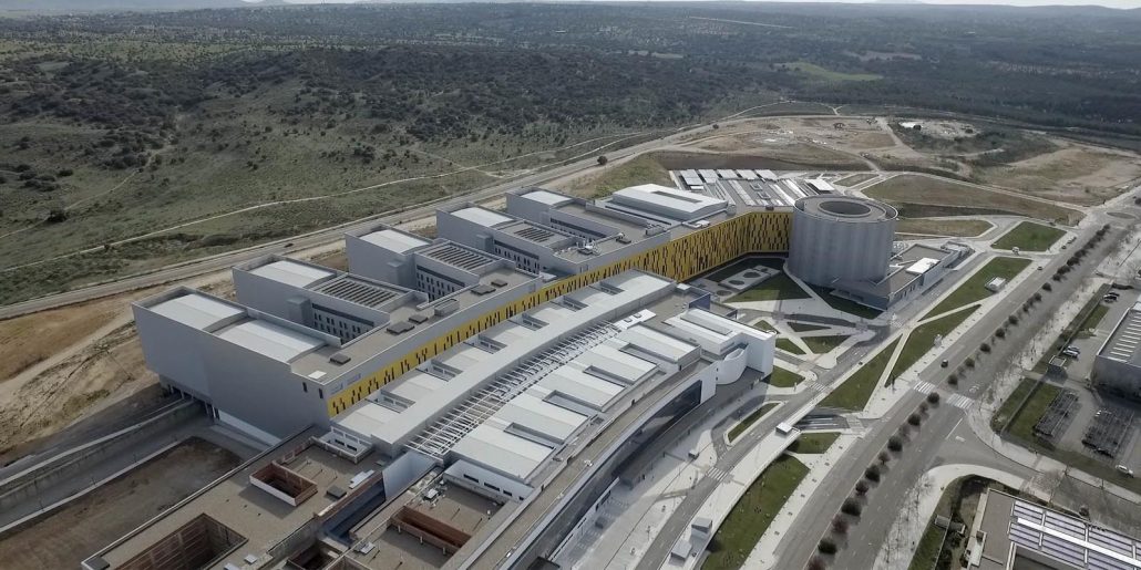
The expansion of Mendizorroza stadium in Vitoria, home to Spain’s La Liga football team Deportivo Alaves, will include energy designed by Genesal Energy.
Should the mains system go down at any time, the Genesal Energy generator will automatically kick in (pun intended), guaranteeing that the thousands of fans watching the match will not miss any of the action in the newly expanded stadium.
The Mendizorroza stadium is undergoing an investment of 50 million Euros, which will include an increase in capacity from 19,800 seats to 32,000. The 62% addition in spectator capacity forms a part of one the most ambitious undertakings to ever happen in the history of Deportivo Alaves. Overall, the expansion is not just about remodelling the stadium, it will also have a positive impact on the surrounding areas.
Settings such as Mendizorroza, are not only used for top flight Spanish football matches, they are also used for large events such as concerts. It means the role of the genset is fundamental in guaranteeing with efficiency the safety and continued enjoyment of events which congregate thousands of people in one place.

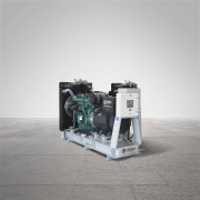
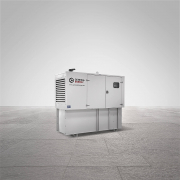
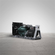
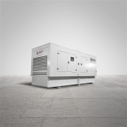
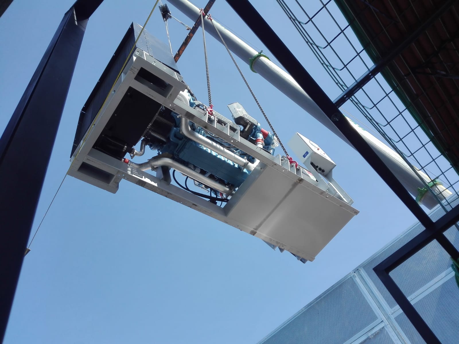
To ensure efficiency and peoples wellbeing are met, the genset supplied by GENESAL ENERGY is very special, designed with a high capacity and an oversized alternator to meet the load peaks that will be demanded from it. The genset offers 650kVA emergency power rating in a sound proofed cabin, and employs a highly reliable engine prepared to immediately take on the required loads in any circumstances should the mains grid itself fail. While also maintaining constant and stable frequency and voltage values.
Oversized Alternator
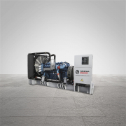
Another of the peculiarities of the genset is its oversized alternator, for supplying the energy needed to the stadiums metal halide lamps. Both in luminosity and colour, these types of lamps are considered very high performance. They do however have an issue, which is the very high voltage peak reached in the start-up and a switch on phase of between 5 and 10 minutes when cold.
The oversized alternator is chosen because the lights will be switched on by the generator when they are already “hot” from being in use via the mains grid. After a mains grid failure this heat causes a highly reactive charge due to the voltage intensity passing through the condensers, which could destabilise the gensets voltage if it is has not been calculated correctly.
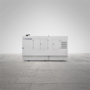
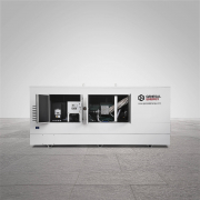
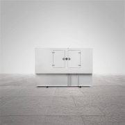
Soundproofed in a specially prepared room
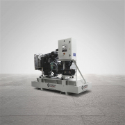
Conscious of the issues faced, Genesal Energy has chosen an alternator specifically designed to supply the required load and re-establish stadium lighting in the minimum time possible.
The Mendizorroza stadium genset includes an electric motor which permits a constant level of frequency for continued power supply, and can recuperate very quickly from the sudden load impact during start-up.
Whilst the genset could easily be installed in the exterior, in this case a made to measure room will be used to place the generator inside, therefore reducing sound emissions and affording a much better acoustic environment in the surrounding area.