Co-Generator Power Plant
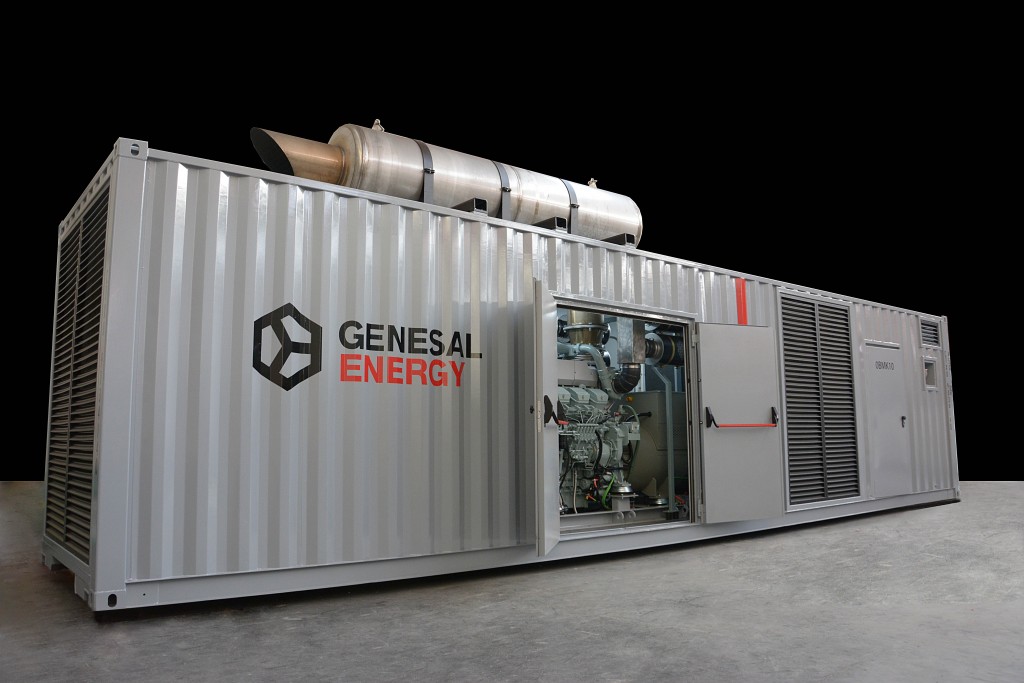
- LOCATION: COATZACOALCOS – MEXICO
- INSTALLED POWER: 1563 kVA Prime Power; 1719 kVA Standby Power; 480/277V 60Hz with a power factor of 0.8.
- SPECIAL CONFIGURATION: A sound-proofed genset which itself is split in to three separate compartments, one compartment being for the joint motor-alternator set up, a compartment which includes the main control and power panel, and finally a compartment containing a 100L fuel tank. The design should follow some engineering specific requirements, including a programmable control panel which features the ability to adapt to the required mode of operation.
PROJECT OBJETIVES
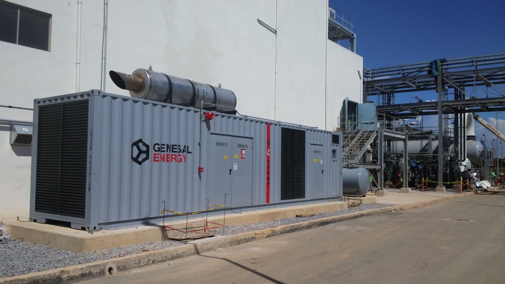
The underlying objectives in this project contained the design, documentation, parts and materials, manufacturing, testing, supply (packaging included), transport and start-up of one diésel genset and associated electrical components. The genset specific use is to give power to low voltage back up auxiliary equipment for the combined cycle generation plant Afranrent in Coatzacoalcos in Mexico.
The combined cycle cogeneration plant in question is for electricity power generation, as well as the production of low pressure steam to power two absorption chillers, which themselves provide ice cold water for a cryogenic plant in the vicinity.
The electrical installation in the cogeneration plant is made up of step-up transformers, the power generation system at 13,8KV, and the auxiliary systems power of 4.16/0.48KV. Energy is generated in the power-plant using a Gas-Turbine with a synchronous generator (output = 135 MVA with a power factor of 0.9, voltage = 13.8 kV ± 10%) and a Steam-Turbine with its corresponding synchronous generator (output = 55,412 MVA with a power factor of 0.85, voltage = 13.8 kV ± 10%). Through the use of step-up transformers or unit-transformers it goes from the generated voltage (13.8KV) to the transmission voltage (115kV). Generated power is then fed in to the grid through a link up sub-station at 115kV
PROJECT DESCRIPTION
The project was developed during the last quarter of 2015. Initial studies on the technical specifications and preliminary designs were done prior to this in the middle of the year. The final specs and design work was approved in September 2015 leading to the contract being awarded to GENESAL ENERGY.
The project was launched in September 2015 at our Genesal European head offices. It was during this meeting that all project decisions were made including planning schedule management, milestones, documentation, and the necessary steps to complete the project.
Following on from the launch of the project detailed planning commenced to set the documented standards in developing the project and ensuring it met the deadline. The documentation included electrical designs, mechanics, signals lists, required materials, testing and all the calculations necessary for the design of the genset in accordance with the specified guidelines set out by ENGINEERING.
Upon completion of the documentation it was sent to the client for their comment and subsequent approval. The next phase was to commence the production of the genset using the finalised and approved design specifications for both electrical and mechanical engineering. At Genesal, mechanical engineering design is done using specialised software with 3D, this guarantees a pre-production design that is 99% of the finished product.
Our electrical engineering design uses a specific design program to complete the electrical plans, single line circuit diagrams, materials required as well as detailed power & control cabinet layout.
When the manufacturing phase commenced the approved designs were strictly followed so that upon entering the in-house testing stage in the presence of the client, they could see this was in line with the testing document as approved by the client
In December 2015 the actual testing phase commenced on-site in Genesal’s main assembly plant, done with client present in order to demonstrate that the mechanical and engineering solutions and accompanying documentation had been adhered to. Checks were also done to ensure that the dimensions of the manufactured genset corresponded to the 3D designs and that all electric circuitry was in accordance with the electrical plans. Additionally (and following a very rigorous protocol) testing of safety alarms, the requested operational functions by the client was carried out. Next and very crucially the genset itself was placed on a load-bank for resistive and inductive testing which fully simulated the eventual working conditions it will operate in. During this final test the motor-alternator operated at 110% of its capacity to ensure the genset could meet the most extreme conditions.
In January 2016 with all the testing successfully completed and along with all the approved documentation, the logistics operation was undertaken to send the genset from our European manufacturing and assembly plant to its final destination at the cogeneration plant of AFRANRENT in COATZACOALCOS, MEXICO.
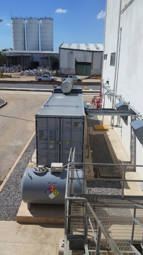
Upon arrival in Mexico the genset was then installed as per the customers’ requirements and the agreed solution. In June 2016 GENESAL ENERGY qualified technicians initiated the start-up process. This consisted of full on-site testing to ensure correct operational functionality, as well as ensuring all the parts and components were in perfect condition. Most importantly the on-site testing phase included the synchronization functions between the genset and the low voltage network which supplies power to the back-up auxiliary equipment. Upon completion of the start-up protocols the genset was finally operational and ready to provide the power when necessary for essential services within the cogeneration facility.
Additionally our technicians gave the operatives in the plant an exhaustive training course on the functions of the genset, its care and also safe working practices.
FEATURES
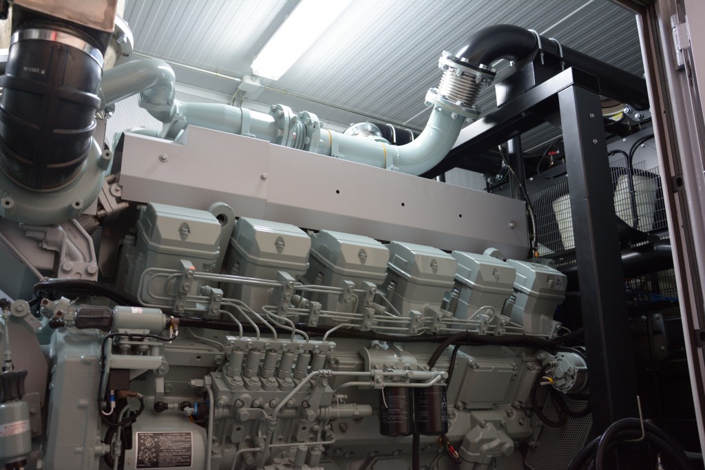
In order to fall within noise level requirements, the genset was acoustically soundproofed on the inside using rockwool, encased in perforated sheet metal for maximum sound absorption. Also, silencers were fitted to air intake and outlet pipes. Also noise reducing filters for waste gas were actually installed within the container to facilitate easier on-site installation.
The container was divided into 3 separate compartments – motor-generator, electrics, fuel tank:
- The engine compartment has two doors, one on each side for ease of access during maintenance operations, as well as normal lighting and emergency lighting.
- The electrics control room contain an exterior access door, normal and emergency lighting as well as climate control. Situated within this compartment are the control panel (automaton, touch screen, protective relays, synchronization etc) and the power control panel (LSIG breakers for output and busbar connectors to power supply wires).
- The fuel holding compartment has exterior door access and internal lighting. Inside is a cylindrical double walled fuel tank with a 1500L capacity.


