Energy to help in natural disasters: we provide tailor-made generators for the Military Emergency Unit (UME)

Established in 2006, the UME has now more than 3.500 personnel and has intervened in more than 600 missions nationally and internationally.
A few weeks ago, troops from the Military Emergency Unit (UME) rescued alive two children and their mother from the debris in the Turkish city of Nurdagi, 5 days after the 7.8-magnitude earthquake that caused more than 40.000 deaths in Syria and Turkey. It’s part of the duty of this Armed Forces Corps to assist in these catastrophes.
The UME has been in the first line of several natural disasters: the La Palma volcano, the Philomena Storm or the recent wave of forest fires in Chile. To handle these situations with maximum guarantees, mobile generator sets for the UME are essential. Furthermore, they have to be specially designed to provide the utmost reliability, robustness and autonomy.
Renewal
Following these criteria, Genesal Energy has tackled the task of renewing the UME’s High Power generator sets. Manufacturing and installing two 300 Prime Power-330 Standby Power generator sets within a container able to operate individually, in parallel or at alternate times.
The main aim of the renewal plan was to satisfy the electrical demand of the unit when intervening in remote areas far from the grid. The designed solution consists of two Stage V emission’s compliant diesel engines and two alternators joined by flexible couplings capable of absorbing vibrations and endure the load steps ensuring the correct operation of the system. No interruptions in extreme situations.
The project was allocated to Genesal Energy after winning the public tender procedure convened by the Ministry of Defence following the requirements from the Unit. The equipment is designed to withstand the most adverse climate conditions and has been manufactured to facilitate maintenance & service.
Features
- ISO 20ft 1CC Container constructed in a modular way with electro welded folded steel plate. Soundproofed with rockwool & micro-perforated sheet acoustic panels. Housing two 300 kVA generator sets.
- Loading & Unloading Hitch according to STANAG 2413 and standardised corners.
- Fitted with wide doors allowing easy access to the interior for inspection and service. They also have position sensors connected to the control panels to indicate open/closed status. Air inlet & outlet ventilation louvers.
- Painted following UNE-EN ISO 12944-2:2018 norm. C5M finishing for highly corrosive environments. RAL3000 finishing colour.
- Interior lighting & emergency lighting.
- Smoke detectors connected to a digital input of the generator’s control panel.
- Stage V emission’s compliant diesel engines.
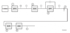
- DOC1, DPF2, SCR3 and ASC4 integrated in just one exhaust gas silencer:
- 3-Phase alternating current, self-regulated, self-excited and brushless alternator.
- Voltage electronic regulator.
- Each engine-alternator block is mounted on an independent base frame. Each fitting a 1.000 L stainless steel integrated fuel tank.
- 2 Automatic fuel transfer pumps, one in each tank, for fuel circulation.
- 2 fuel nozzles in each tank, one on each side, for easier filling.
- Antivibration mountings between the engine-alternator block and the base frame.
- The base frames are fixed to the container by adjustable handles for easy pinning & unpinning manoeuvres.
- The exhaust system consists of manifolds, pipes and silencers mounted INSIDE the container. It includes the DOC, DPF, SCR and ASC needed for the Stage V emission’s compliance. It is fitted with piping flanges and a flexible tube to avoid thermal dilatation affecting the installation.
The Control panel is located in the opposite side of the container’s lifting hitch for safer set operation. It has the following characteristics:
- IP54 cabinet with room enough for every control equipment.
- Thermomagnetic breakers for each circuit.
- 2 synchronisers/control panels to manage both engine-alternator blocks.
- Engine battery power supply (no need for external power supply start).
- Rack battery charger maintaining optimal charge level at all times.
- Internal lighting with limit switch.
- Schuko-type plug for PC or other low power consumption appliances.
- Relays and contactors for Start & Stop procedures.
- Terminal boxes and ancillary materials.
- Connectors for engine-alternator & control panel cabling, easier to disconnect. These connectors are codified in a way that the change of position of the sets within the container produces an on-screen alarm in the panel. This alarm DOES NOT impede the starting of the sets.
- ComAp InteliGen Control Panel.
The front of the Panel contains all the controls:
- Visual control display.
- Aut./Man. Operation selector switch.
- Configuration selector switch.
- Emergency Stop.
- Alarm acoustic indicator. Auto switch-off after 30”.
- RJ45 connector for external communications.
A Power Board is also located in this area, containing:
- IP45 metallic cabinet containing all the power equipment.
2 Circuit Breakers, one per power outlet, featuring:
- Rated current: 630A
- Short-circuit current: >3kA
- Rated voltage: >400V
- Ancillary equipment: 230v 50Hz motor, minimum voltage release coil, auxiliary contacts.
- Busbar between both Circuit Breakers for parallel operation.
- 1 Main Genset Circuit Breaker for the whole island:
- Rated current: 1200A
- Rated voltage: 400V
- Ancillary equipment: 230v 50Hz motor.
- Protection: L i
- Anti moist heating resistor with thermostat for temperature control.
- Internal lighting with limit switch.
- Connectors for engine-alternator cabling, easier to disconnect.
In the lower part of the Control area of the container a Socket Panel is located containing:
- 10 x CETAC 63A 3P+N+T
- 6 x CETAC 32A 3P+N+T
- 4 x CETAC 16A 2P+T
- Harting connectors for parallel connection to existing gensets.
- Load banks are fitted within the container to ensure a minimum load of 40% to prevent low-load operation at any time.
Equipment: ISO20 FT 1CC Soundproofed Container
Prime Power: 2 x 300 kVA
Standby Power: 2 x 330 kVA
Voltage: 400/230V
Frequency: 50Hz
RPM: 1500
Engine: Stage V VOLVO
Alternator: Leroy Somer