Made to measure energy solution for the Almaraz Nuclear Power Plant

Both the reactors at the Almaraz Nucelar Power Plant in Caceres (the oldest in Spain) supply 7% of the nations energy demands. The plant is located in an area know as Ribera del Rio Tajo, and they have recently placed their trust in GENESAL ENERGY to design an emergency back up generator set capable of dealing with any potential incident.ualidad.

The project consisted in designing, building, installing and commissioning a genset capable of supplying a 110kVA of power to supply energy to the Individual Temporary Storage (ITS), which alongside the fuel pools, allow for temporary storage of used combustibles from the reactors in the event of a power failure.

Genesal has designed a soundproofed genset inside a 20ft container with an interior control room configured for automatic start up. The bench frame incorporates a 700 litre fully bunded fuel tank, providing the genset with up to 25 hours autonomy. The genset has been specially designed to work at 45°C as well as resist seismic movements, in order to comply with security norms.

To meet with the client’s specific needs the genset was designed with an independent control room and power output with various local controls to manage the genset and other parts of the installation.

Load bank

In the switchgear output of the grid/genset, switches are fitted for each area of the ITS in the power plant. Each one can close or open via pushbuttons or using a pre-programmed sequence designed by the client.

For the correct functionality of the genset, a separate room within the container was built to hold a resistive load bank which is connected to the genset output always and when the load is less than 40% of its maximum capacity. This allows for fuel use optimization and prolongs the lifetime of the genset (normally a genset is recommended to work at 70/80% of its maximum).

The load bank can connect to the genset manually via pushbutton for maintenance work. It is also important to highlight the implementation of signals exchange in the Distributed Control System (DCS) of the power plant, for example the state of switchgear, of the genset and a measurement of zero return to detect grounding failure in the installation.

Technical Data

  • Power PRP: 100kVA
  • STP Power: 110kVA
  • Frequency: 50 Hz
  • Voltage: 400/230V
  • Fuel Tank: Fully bunded, bench frame integrated with 700 litre capacity
  • Pre-heating resistance
  • Seismic resistant genset, includes anti-shear dampers
  • Size: 6058mm x 2438mm x 2591mm
  • Resistive load bank
  • Manual pump for diesel filling
  • Control panel with automatic start-up in case of grid failure
  • Control of input of manual loads and automatic sequencing (as per client’s spec)

Combined Cycle Power Plant – Mexico

_EDU4021-Editar

PROJECT ID Combined Cycle Power Plant, Valle De Mexico II
OUTPUT 1980/2178 kVA
TYPE Soundproofed
SPECIALLY CONFIGURED Genset manufactured according to a range of specific conditions as determined by the engineering


GENESAL ENERGY has supplied an emergency power genset with a power rating of 2178 kVa which will be used as a back-up for the Combined Cycle Power Plant Valle de Mexico II in the municipality of Acolman (Mexico State). Once finalised the plant itself will have an output power capacity of 615 MW and will operate with natural gas, at an approximate cost of 700 million $USD in construction investment.

The power plant itself will contribute to a 4 % increase in available energy to meet the growing energy needs in the centre of the country.

This particular project has been delivered in conjunction with our GENESAL ENERGY Mexican branch, which has for many years contributed and supported the growth of the Mexican energy sector.

DOWNLOAD PROJECT INFO HERE

Co-Generator Power Plant

dsc_9462

DOWNLOAD PROJECT INFO HERE

  • LOCATION: COATZACOALCOS – MEXICO 
  • INSTALLED POWER:  1563 kVA Prime Power; 1719 kVA Standby Power; 480/277V 60Hz with a power factor of 0.8.
  • SPECIAL CONFIGURATION: A sound-proofed genset which itself is split in to three separate compartments, one compartment being for the joint motor-alternator set up, a compartment which includes the main control and power panel, and finally a compartment containing a 100L fuel tank. The design should follow some engineering specific requirements, including a programmable control panel which features the ability to adapt to the required mode of operation.

PROJECT OBJETIVES

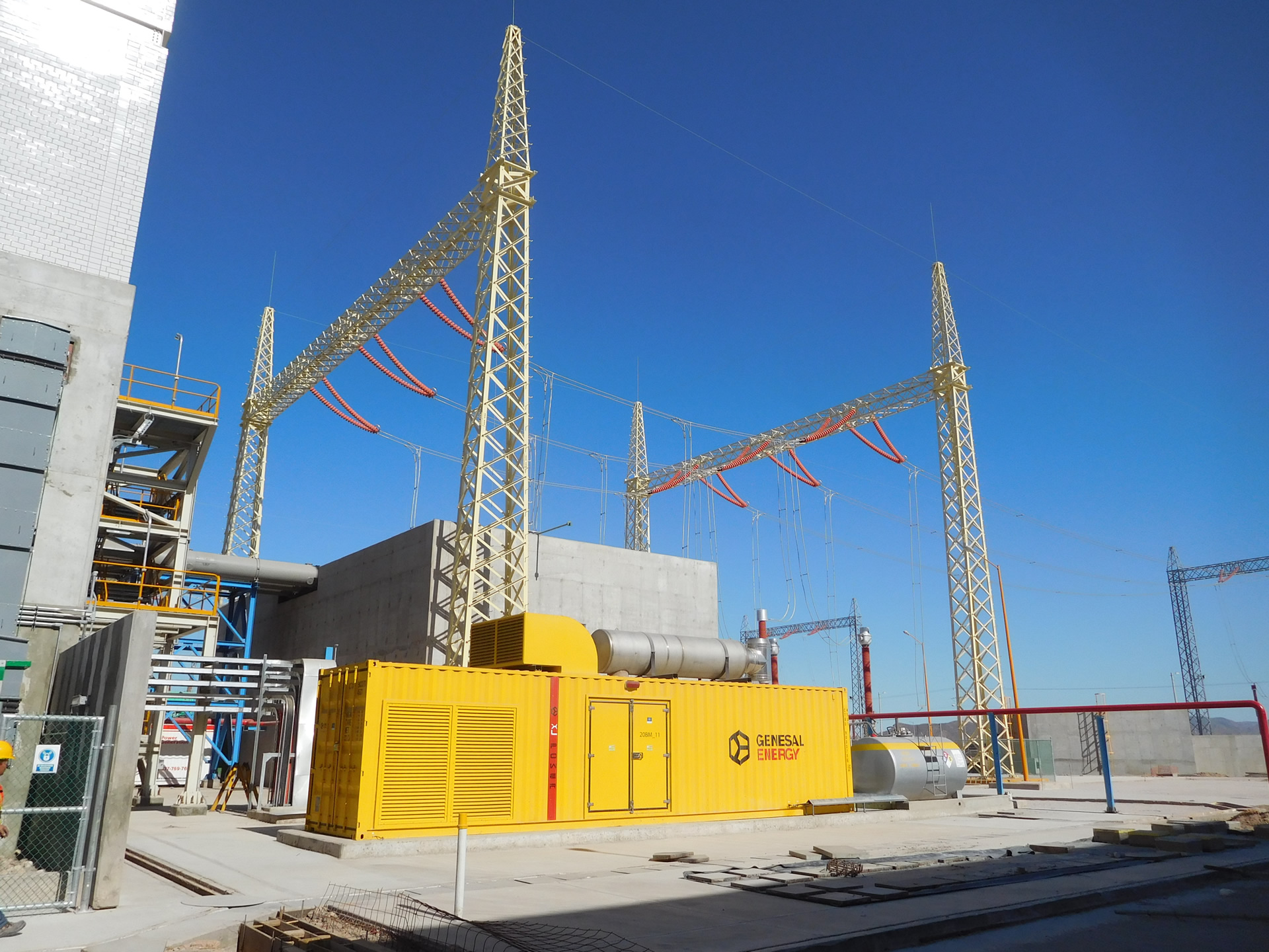
The underlying objectives in this project contained the design, documentation, parts and materials, manufacturing, testing, supply (packaging included), transport and start-up of one diésel genset and associated electrical components. The genset specific use is to give power to low voltage back up auxiliary equipment for the combined cycle generation plant Afranrent in Coatzacoalcos in Mexico. 

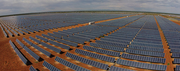
The combined cycle cogeneration plant in question is for electricity power generation, as well as the production of low pressure steam to power two absorption chillers, which themselves provide ice cold water for a cryogenic plant in the vicinity.

The electrical installation in the cogeneration plant is made up of step-up transformers, the power generation system at 13,8KV, and the auxiliary systems power of 4.16/0.48KV. Energy is generated in the power-plant using a Gas-Turbine with a synchronous generator (output = 135 MVA with a power factor of 0.9, voltage = 13.8 kV ± 10%) and a Steam-Turbine with its corresponding synchronous generator (output = 55,412 MVA with a power factor of 0.85, voltage = 13.8 kV ± 10%). Through the use of step-up transformers or unit-transformers it goes from the generated voltage (13.8KV) to the transmission voltage (115kV). Generated power is then fed in to the grid through a link up sub-station at 115kV

20160614_154828

PROJECT DESCRIPTION

The project was developed during the last quarter of 2015. Initial studies on the technical specifications and preliminary designs were done prior to this in the middle of the year. The final specs and design work was approved in September 2015 leading to the contract being awarded to GENESAL ENERGY.

The project was launched in September 2015 at our Genesal European head offices. It was during this meeting that all project decisions were made including planning schedule management, milestones, documentation, and the necessary steps to complete the project.

Following on from the launch of the project detailed planning commenced to set the documented standards in developing the project and ensuring it met the deadline. The documentation included electrical designs, mechanics, signals lists, required materials, testing and all the calculations necessary for the design of the genset in accordance with the specified guidelines set out by ENGINEERING.

Upon completion of the documentation it was sent to the client for their comment and subsequent approval. The next phase was to commence the production of the genset using the finalised and approved design specifications for both electrical and mechanical engineering. At Genesal, mechanical engineering design is done using specialised software with 3D, this guarantees a pre-production design that is 99% of the finished product.

20160614_155730

Our electrical engineering design uses a specific design program to complete the electrical plans, single line circuit diagrams, materials required as well as detailed power & control cabinet layout.

When the manufacturing phase commenced the approved designs were strictly followed so that upon entering the in-house testing stage in the presence of the client, they could see this was in line with the testing document as approved by the client

In December 2015 the actual testing phase commenced on-site in Genesal’s main assembly plant, done with client present in order to demonstrate that the mechanical and engineering solutions and accompanying documentation had been adhered to. Checks were also done to ensure that the dimensions of the manufactured genset corresponded to the 3D designs and that all electric circuitry was in accordance with the electrical plans. Additionally (and following a very rigorous protocol) testing of safety alarms, the requested operational functions by the client was carried out. Next and very crucially the genset itself was placed on a load-bank for resistive and inductive testing which fully simulated the eventual working conditions it will operate in. During this final test the motor-alternator operated at 110% of its capacity to ensure the genset could meet the most extreme conditions.

In January 2016 with all the testing successfully completed and along with all the approved documentation, the logistics operation was undertaken to send the genset from our European manufacturing and assembly plant to its final destination at the cogeneration plant of AFRANRENT in COATZACOALCOS, MEXICO. 

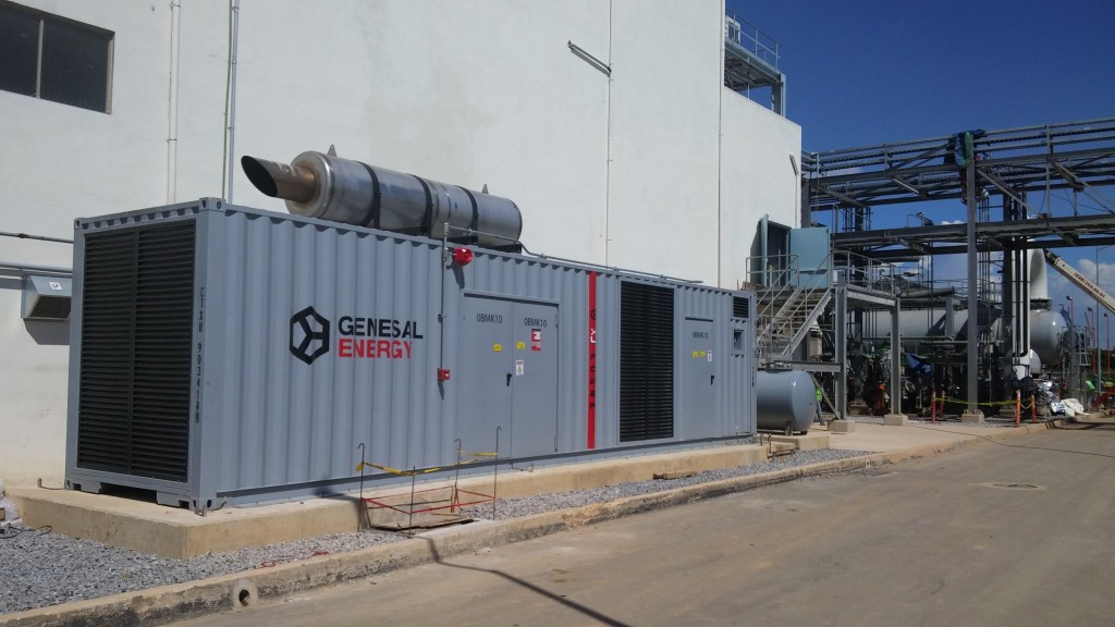
Upon arrival in Mexico the genset was then installed as per the customers’ requirements and the agreed solution. In June 2016 GENESAL ENERGY qualified technicians initiated the start-up process. This consisted of full on-site testing to ensure correct operational functionality, as well as ensuring all the parts and components were in perfect condition. Most importantly the on-site testing phase included the synchronization functions between the genset and the low voltage network which supplies power to the back-up auxiliary equipment. Upon completion of the start-up protocols the genset was finally operational and ready to provide the power when necessary for essential services within the cogeneration facility.

Additionally our technicians gave the operatives in the plant an exhaustive training course on the functions of the genset, its care and also safe working practices.

FEATURES

dsc_9472-retocada dsc_9500

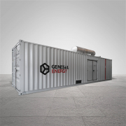
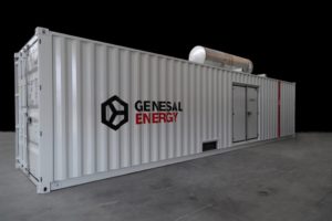
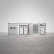
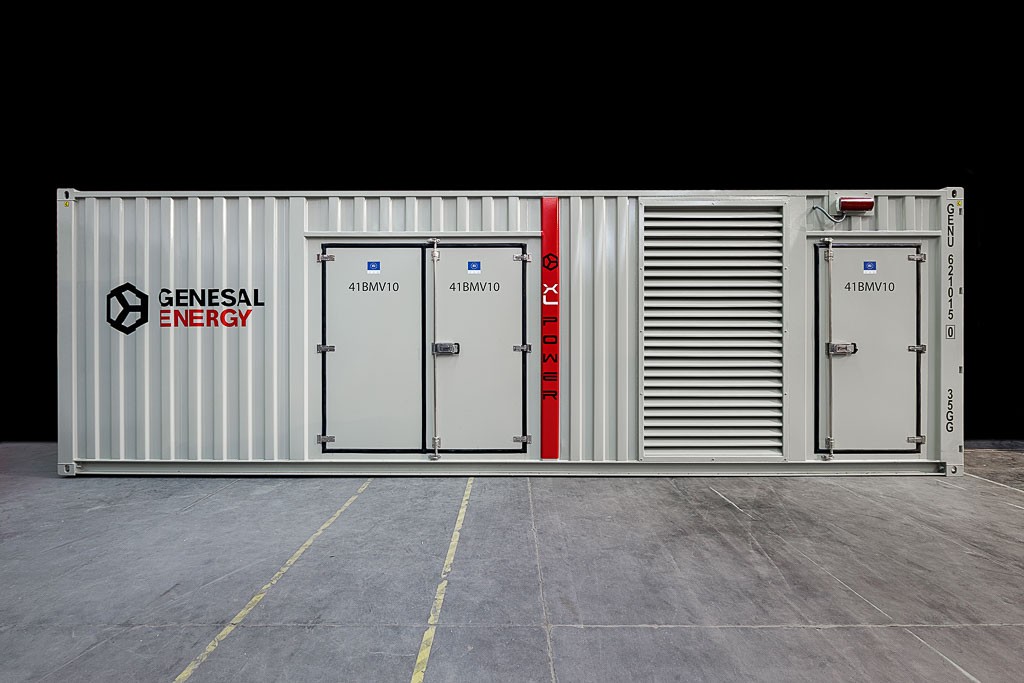
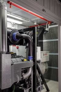
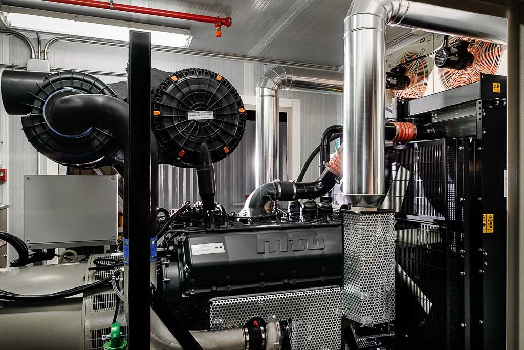
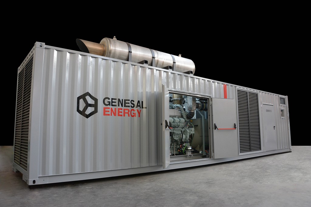
In order to fall within noise level requirements, the genset was acoustically soundproofed on the inside using rockwool, encased in perforated sheet metal for maximum sound absorption. Also, silencers were fitted to air intake and outlet pipes. Also noise reducing filters for waste gas were actually installed within the container to facilitate easier on-site installation.

The container was divided into 3 separate compartments – motor-generator, electrics, fuel tank:

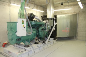
  • The engine compartment has two doors, one on each side for ease of access during maintenance operations, as well as normal lighting and emergency lighting.
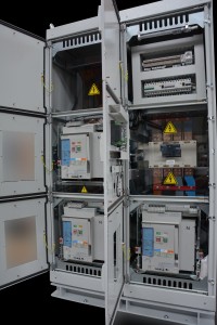
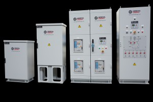
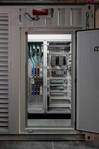
  • The electrics control room contain an exterior access door, normal and emergency lighting as well as climate control. Situated within this compartment are the control panel (automaton, touch screen, protective relays, synchronization etc) and the power control panel (LSIG breakers for output and busbar connectors to power supply wires).
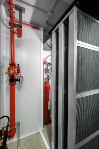
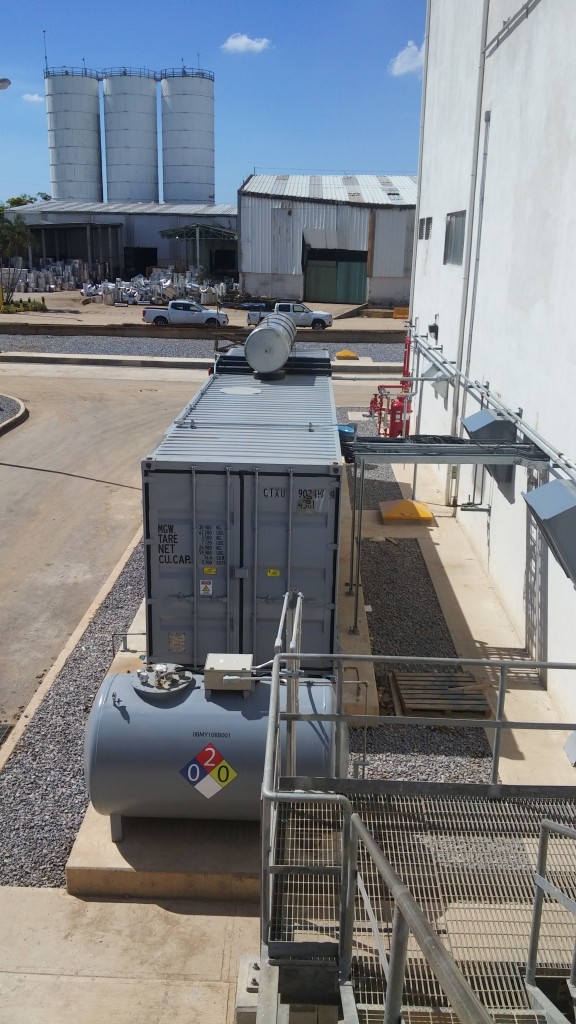
  • The fuel holding compartment has exterior door access and internal lighting. Inside is a cylindrical double walled fuel tank with a 1500L capacity.

Power supply for Spain’s most important Nuclear Power Plants

LOCATION: NUCLEAR POWER PLANTS, SPAIN (COFRENTES, ALMARAZ and TRILLO) 

INSTALLED POWER: Prime power 630kVA; Standby power 700kVA; 400/230V 50Hz with output factor of 0.8.

Special Configuration: Gensets, control panels, changeover control and power panel, connection panels, fuel transfer pump, specially built to withstand earthquakes as per seismic definitions and norms stated in “IEEE 344 Standard for Seismic Qualification of Equipment for Nuclear Power Generating Stations”

65755_7image154naom_571f3ea77453a

PROJECT AIMS

The goal of this project was the successful installation andl start-up for 3 gensets with their respective control panels to provide power for the ALTERNATIVE EMERGENCY CONTROL CENTRE (AECC) in the three distinctive Nuclear Power Plants. The focus was on a fully integrated star to finish project and included the; design, documentation, manufacturing, testing, seismic certification, supply, and logistics.

In the after math of the Fukushima-Daiichi Nuclear Power Plant incident in Japan during the tsunami of 2011, the Western European Nuclear Regulators Association (WENRA) defined amongst other factors, the stress tests to be carried out in European Nuclear Power Plants.

As a result of these evaluations the Spanish Nuclear Safety Council (CSN) requested that each nuclear power plant should create an alternative centre to implement and continue emergency operational management should a situation arise forcing the evacuation or abandonment of the Centre for Operational Support and the Technical Support Centre, and as determined by the assessment of the power plants director. The CSN determined that the implementation of the ALTERNATIVE EMERGENCY CONTROL CENTRE (AECC) should be carried out in all the Spanish nuclear power plants.

PROJECT DETAILS

dsc_4048

This particular project was developed in the first half of 2015. The initial study of the technical specifications and the preliminary designs were undertaken during the last quarter of 2014. GENESAL was finally awarded the contract by the client in early 2015. On the date the contract was formally agreed a meeting was held to launch the project in the clients offices during which the project timing and delivery, stages, documentation and the steps necessary to reach a successful conclusion, were established.

As we were dealing with a “critical” project, classed as a last resort energy powered solution in the event of the requirement to shut down the nuclear reactor due to an emergency or natural disaster, we focused the first stage of the project on the development of prototypes of each individual generator. This then led on to seismic resistance testing for the gensets based on the estimated seismic activity levels which could occur in their operational location. The results determined that the Genesal prototypes were able to withstand this potential seismic activity and continue functioning correctly after a potentially serious incident.

dsc_4074-copia

During the design phase of the prototypes, we undertook a serious of diverse seismic studies with the collaboration of the Mechanical Engineering department of the University of La Coruna in North West Spain. Simulations were carried out to study the behaviour of the different control panels, floor fixings, and the genset support frame with a 700 litre fully enclosed fuel tank. Upon completion of the testing and simulation, and with the design approved by the client, we constructed the pro-types. These were subsequently sent to a laboratory specialising in vibration where seismic testing was done and validated satisfactorily allowing for production of the final product in series.

SOLUTION

Upon completion of the gensets and their validation by the CSN (Spanish Nuclear Safety Council), they were installed in the ACEM (Alternative Centre for Emergency Management) in a specially designed room for the genset and associated control features. The genset and control elements then went through the start-up procedure and were incorporated into the management systems of the power-plant.

1-img_9488-copia

SEISMIC TESTING

As determined by the “IEEE 344 Standard for Seismic Qualification of Equipment for Nuclear Power Generating Stations, and the seismic response spectra as provided by our client (which reached 3g, we carried out the seismic validation testing procedures of all the equipment involved for each individual nuclear power plant using two different methods:

• A computer simulation was carried out with the University of La Coruna in North West Spain. The following – components were tested:

– control panels,

– changeover control and power panel,

– connection panels,

– secure floor fixings

– fuel transfer pump

Once manufactured, all the parts were sent to a laboratory specialising in vibrations to seismically validate and certify them in accordance with the requirements of IEEE 344. We should highlight that upon successful completion of the testing all the parts used were disposed of as they are now not considered apt for end user facilities, and new identical parts are built.

• In the case of the Genset as a whole, due to the elevated investment required, the validation of each unit was carried out through simulations, calculations and reports on finite materials. Testing requirements were in line with those as determined by the standards incorporated in IE344 as well as the Eurocodes standards for structural design in order to calculate the legs and the secure floor fittings.

More information here

Combined Cycle Plant GEN750TC

CASE STUDY

Emergency diésel power generator to be installed in a Combined Cycle Plant in Chilca, Lima province, Peru. The plant has a General Electric gas turbine and a Siemens steam turbine , capable of generating a net 110 MWe.
OVIDIO ALDEGUNDE

REQUIREMENTS

  • Space limitations.
  • Internal division between 3 rooms: generator room, control room and tank room. The control room must be climate-controlled.
  • 6 hours of independent operation at 100% load.
  • Corrosive atmosphere with high content of suspended dust.
  • Maximum noise level 85 dBA at a distance of 1 metre.
  • Fire detection and extinguishing system.

OVIDIO ALDEGUNDEOVIDIO ALDEGUNDE    OVIDIO ALDEGUNDE

UNIT DESIGN

Based on a study of the loads to be supplied, the selected power unit had a rating of  680/750 kVA, 60 Hz, 480 V. To meet the requested specifications, GENESAL ENERGY chose the following solutions:

  • To overcome the space limitations, the unit was assembled in a 30’HC container designed especially for the project.
  • The unit as required was divided in to 3 rooms:
  1. Generator room: Containing the power generator along with the batteries.
  2. Control room: The control panel and generator power panel are installed in this room. The wiring connections are located at the bottom of the generator.
  3. Tank room: A custom-made, approved, 1500 litre double-walled parallel piped-shaped tank was installed, guaranteeing 6 hours of independent operation at full load.
  • Because the atmosphere where the generator would be operating is highly corrosive (marine atmosphere), it was painted in accordance with ISO 12944, following a C5M diagram, which consists of type SA 2 ½ shot blasting in accordance with ISO 8501, one initial 80 µm coat of zinc-rich paint, two 100 µm coats of epoxy paint and a final, 100 µm coat of polyurethane paint (RAL 7032), giving a total dry film thickness of 380 µm.
  • The atmosphere where the generator is located has a high content of suspended dust. Therefore, powered grilles were installed on the generator’s air intake and outlet. The slats open when the generator is operating and close automatically when the generator shuts down.
  • To meet the noise requirements, the generator was attenuated with acoustic panels consisting of rock wool and perforated plates, and was equipped with noise reducing filters on the air intake and outlet. The exhaust soundproofing was installed inside the container to avoid complications during the on-site installation.
  • The fire extinguishing system includes a detection component consisting of a smoke detector system in all 3 rooms aswell as an extinguishing system that uses water mist in the engine room and tank room, and CO2 in the control room.
  • The control panel was designed to meet the specific requirements of the project engineering team.
  • Redundant programmable automaton.
  • Fibre optic communication with the redundant DCS by modbus TCP/IP
  • 4” touchscreen
  • Protection relay meeting the following ANSI-based electrical protection requirements: 50, 51, 51N, 59N, 59, 27, 81m, 81M, 46, 49, 25, 78, 32, 40
  • Protection relay meeting the following ANSI-based electrical protection requirements: 87G, 24
  • Synchronizer between generator and networks

OVIDIO ALDEGUNDECombined Cycle Plant GEN750TC

Super-compact GEN33D Power Generator

gen33d-1

Application: auxiliary power generator for special vehicles.

Power: 30 kVA DC, 33 kVA emergency supply.

Special configuration: super-compact power generator.

SPECIFICATIONS

  • The power generator has to be installed in a small compartment measuring only 1105 x 950 x 750 mm (length x width x height).
  • We have to adapt the installation to the existing air inlets and cooling air outlets in the vehicle.
  • The power generator has to have a power of at least 30 kVA.
  • Integration with the vehicle’s electrical system.
  • High cooling capacity and ability to work with overloads at high temperatures.
  • Capable of withstanding the typical motion of a vehicle of this kind over rugged terrain.

CASE STUDY

A series of questions have been raised at engineering level:

We have been informed of the need to provide power for high-tech auxiliary electronic equipment located in a special vehicle. The equipment has to be able to operate during long daily periods under adverse conditions (high temperatures), with a load of practically 100%.

Its position in the vehicle must ensure that maintenance can only be carried out from one side, as the outer housing is armoured, and only one of the protective covers can be removed. The air outlet must be located on the top, and the air inlet on the bottom, due to the design of the vehicle.

The ultra-compact layout of the cabin and size/power of the motor means that we have to consider a design in parallel to the monoblock, with a power transmission using a toothed belt. The bottom support for the power generator must also be as low as possible to avoid exceeding the necessary height, which means that the crankcase must be at a distance of only 10 mm from the ground, and the bottom support must have an opening so that it can be fitted in place. A series of anti-vibration mountings have been installed to prevent shearing, which are capable of withstanding the movements and acceleration caused by the vehicle during its normal operation.

Finally it has been decided to use a refrigeration system using an oil-cooled motor instead of a more conventional water-cooled motor. These oil-cooled motors can reach much higher operating temperatures, under the same environmental conditions. In a conventional water-cooled motor, the maximum temperature that can be reached by the coolant is normally 100ºC, while in the case of an oil-cooled motor, this temperature can reach 135ºC, which means that the equipment can operate at environmental temperatures of 50ºC without any loss of performance. Also, there are two funnels for channelling the inlet air (cold air from the bottom part) and outlet air (hot air from the upper part), so that the air circulates correctly and cools the equipment properly.

The electrical installation is supplied separately and in different modules, so that it can be integrated into the vehicle’s control panels that allow it to be controlled from the interior, even if the equipment is installed in an external compartment.

 Super-compact GEN33D Power Generator

gen33d-2